

Title: How to Model a Graphene Nanotube in AutoCAD
(how to model a graphene nanotube in autocad)
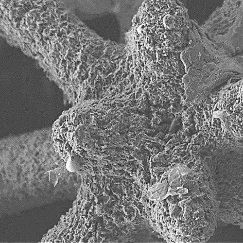
Graphene, the world’s most conductive material, has gained significant attention in recent years due to its unique electronic and mechanical properties. As a result, many researchers and engineers are interested in modeling graphene nanotubes (GNTs) in AutoCAD to gain a better understanding of their structure, behavior, and potential applications. In this blog, we will provide an overview of how to create a GNT model using AutoCAD.
1. Setting Up AutoCAD:
Before creating a GNT model in AutoCAD, you need to ensure that your system is set up correctly. This includes installing the necessary software, setting up AutoCAD preferences, and ensuring that all necessary resources are available. You can download AutoCAD from the official website (
2. Choosing a NUCLEO F9846A microcontroller:
To model a GNT, you will need a microcontroller capable of performing calculations and managing communication with external sensors or devices. The NUCLEO F9846A is a popular choice for its low power consumption and easy-to-use interface.
3. Creating a Material Structure:
To model a GNT in AutoCAD, you first need to create a material structure that represents the graphitic layer on top of the metal substrate. You can do this by creating a new solid object and selecting the appropriate material type. Once the material has been created, you can add features such as edges, corners, and openings to represent the different regions of the GNT.
4. Modeling GNT Nodes:
Once you have created a material structure, you can start modeling GNT nodes within it. These nodes will be responsible for transmitting signals between neighboring layers of the GNT. To create a GNT node, select the appropriate GNT node object from the Object Library. From there, you can add points to represent the location of the node.
5. Interfacing with External Devices:
In addition to modeling GNT nodes, you may also want to integrate them with external devices or sensors. To do this, you can use AutoCAD’s built-in serial communication tools to send commands to the microcontroller or communicate with other devices via I2C or SPI protocols.
6. Fine-Tuning the Model:
After completing the initial modeling process, you should fine-tune the GNT model to ensure that it accurately represents the real-world geometry and behavior of the GNT. This may involve adjusting the dimensions and shape of the nodes, modifying the arrangement of edges and corners, and testing the model to ensure that it works as expected.
Conclusion:
(how to model a graphene nanotube in autocad)
Modeling a graphene nanotube in AutoCAD involves several steps, including choosing a suitable microcontroller, creating a material structure, modeling GNT nodes, interfacing with external devices, and fine-tuning the model. By following these steps and carefully designing each component of the GNT model, you can gain valuable insights into its structure, behavior, and potential applications.
Inquiry us
